Step 4: Download Arduino IDE
You have to download and install a piece of software called Arduino IDE (to later use the Arduino board).
- Go to https://www.arduino.cc/. On the top bar click the SOFTWARE button.
- Scroll down a little bit. Below the title DOWNLOAD, you will see a box called Arduino IDE 2.3.2. On the right side of the box choose the operating system your computer uses. Click on Windows, MacOS X or Linux.
- Another window opens. Click on JUST DOWNLOAD.
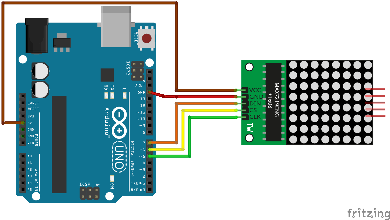
Prepare the Arduino board. Before we start, we need to connect the Arduino board to the 8×8 LED matrix with MAX7219 board. The MAX7219 board has 5 connection points (pins) that need to be connected to the Arduino board. These connection points are a set of wire tips that looks like a fork. To connect them we are going to use the connector wires (jumper wires).
All connector wires are the same, the only difference is the color that covers them. These colors help us identify what kind of data (information) they are carrying. Each connector pin has a specific function, so they cannot go in any order or be connected to just anything. Below I show you the schematic where you can see which pin of the Arduino board you should connect to which pin on the MAX7219 board. Follow the color system of the wires so you don’t make a mistake. Once you make these connections, you are ready to connect the Arduino board to your computer.
Connect the Arduino board to your computer. Now we need to install and configure the Arduino software so that when we connect the Arduino board to the computer, the software recognizes which Arduino board and which USB port we are using.
- Open the Arduino software you downloaded to your computer. Install it just as you would any other piece of software (the process is super simple).
- Connect the USB cable. The B-type end connects to the Arduino board and the other A-type end connects to an available USB port on your computer.
- In the Arduino software (IDE), go to the top bar where it says TOOLS, and then go down up to the menu that says BOARDS: choose Arduino UNO (the name and model of this type of board). At this point the Arduino software already knows that you are going to work with the Arduino UNO board.
- Finally you have to tell the Arduino software which USB port you are going to use. This varies depending if you use a Mac or a PC. Go back to TOOLS and then click on PORT. On a Mac you have to choose the option that starts like this: “/dev/tty.usbserial-” and then some numbers follow. For PC you have to choose “COM“. Usually it is the one with the highest number.
Step 5: Install a library
We must install a library (a kind of codec)to use the 8×8 LED matrix with MAX7219 board. The library is called “LedControl“. We are going to use the Library Manager of the Arduino software to do it.
- Open the Arduino software and click on the SKETCH menu and then go to INCLUDE LIBRARY > MANAGE LIBRARIES.
- The Library Manager will open and you will find a list of libraries that are already installed or ready for installation.
- Scroll down the list and find the ones called “LedControl“. Click on it. You can also search for it by typing its name in the search bar at the top right.
- Finally, click on install and wait for the Arduino software to install this library. Downloading may take some time depending on your the speed of your Internet connection. Once it has finished, an INSTALLED tag should appear next to the “LedControl“ library in the Library Manager. You can now close the Library Manager.
Step 6: Coding in Arduino
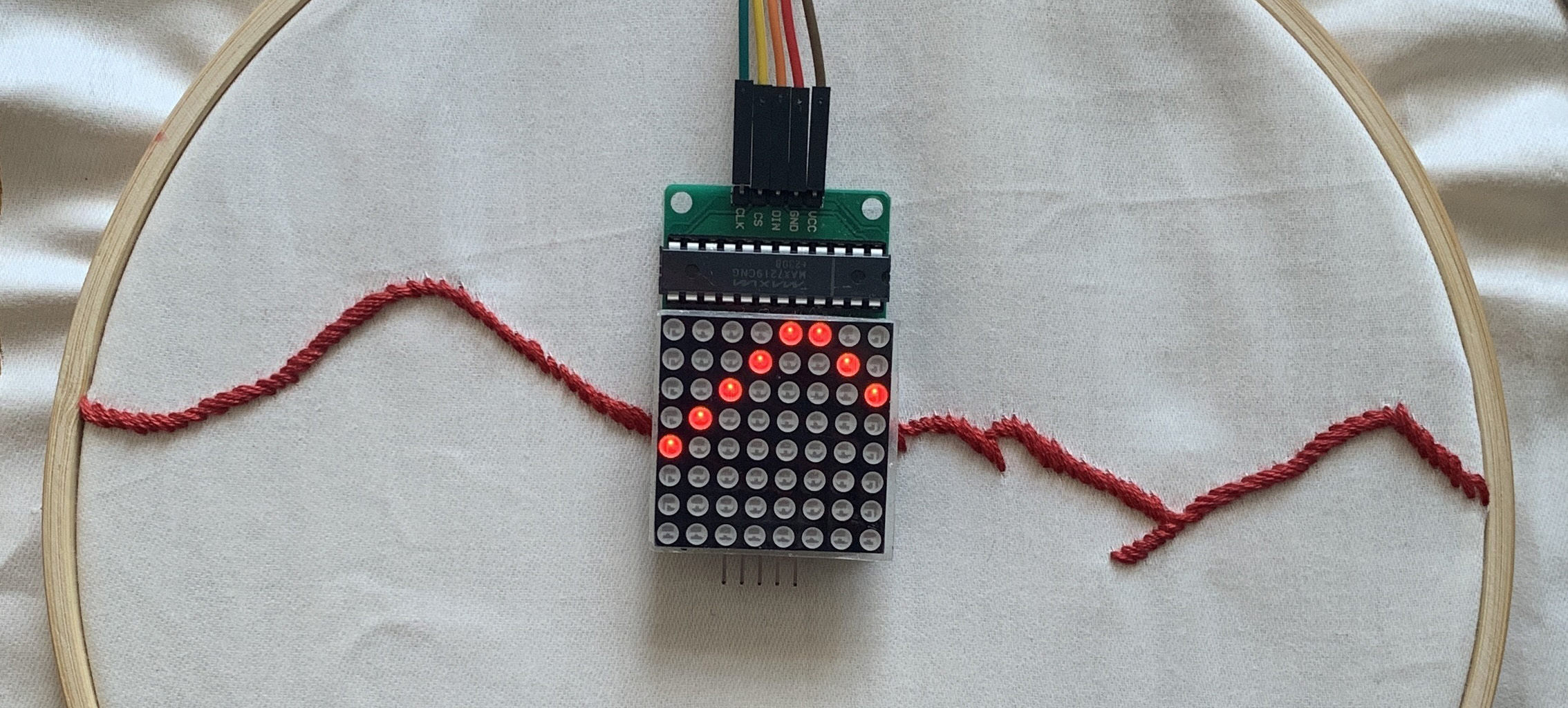
Now we must transfer the silhouette section that we need to complete the silhouette on our canvas to the LED screen. For that, we will write a small piece of code so that the LEDS with MAX7219 board turn on and off. With this little code, we will draw a pattern choosing which LEDs we want to be on. We can also set the duration of a LED being on.
- Download the “8x8_example“ folder and save it on your computer. In the “8x8_example“ folder double click on the “8x8_example.ino“ file. It should open in the Arduino software.
- You will see a small code with an example of how to program, or draw, a letter “A“ on the LEDS matrix with MAX7219 board.
- Read the code and try to get a rough idea of each step.
- Verify in the Arduino software that the code is loaded correctly by clicking on the check icon (✓) in the upper left corner.
- Now we will upload the code we have in the Arduino software to your Arduino UNO board. This is the way in which the Arduino can run the MAX7219 board – turn on and off the LEDs. To do it, click on the UPLOAD arrow icon (→) in the upper left corner.
- After a few seconds (the time the code needs to travel from your computer to the Arduino board) the LEDS matrix with MAX7219 board should light up in the form of a letter “A“ for 5 seconds.
- Now it’s your turn to draw the piece of the silhouette you want. To do this you have to code a pattern.
Step 7: Draw your own pattern.
This is the last part. We have to translate the piece of silhouette your left undrawn on your canvas into LEDs by turning them on and off. To do this we draw a pattern (or many) and translate it into binary code – we have to speak the same language as the Arduino system for coding this.
- Download the document “pattern-led.pdf“. In case you have the book in your hands, look in the envelope behind the exercise for the pattern for setting up the 8×8 LED matrix with MAX7219 board .
- Follow the instructions in that document. As you will see, it’s basically like filling in circles with a pencil. The circles filled in are a 1, and those left blank are a 0. Draw your pattern and translate it into binary on the same sheet (pattern-led.pdf).
- Once you have drawn/coded your pattern, go back the Arduino 8x8_example. Read carefully all the informative notes I left you in the code and the example towards the end. Replace the “A“ pattern of the example with your own pattern. That is, replace the sequences of zeros (0) and ones (1).
- Verify the code with the check button (✓).
- Assuming that the Arduino board is still connected to your computer, we now upload the code you just “drew“ to the Arduino board. Use UPLOAD arrow icon (→).
- Check visually if the coordinates (the position of the LEDs turning on) are correct – we usually make mistakes on the first try. You can modify it and iterate following the instructions above. You can also include other patterns and even create motion.
- When you are happy with the result, you ready to attach the LED display to your canvas with the beige thread in order to complete the silhouette you embroidered there – to complete your memory.